
If Windows does not automatically install them, download and install drivers from http://www.ftdichip.com/Drivers/VCP.htm. Open the Device Manager and check to see if any new devices appear when the control box and PC are connected via USB cable - the primary control board may appear as a USB Serial Converter or a mouse instead of a COM port. If this is the case, right click on the device and navigate through the tabs to the "Load VCP" checkbox which should override the normal driver functions and allow it to function as a Virtual COM Port.
If UV light is present (confirm visually, wearing appropriate eye
protection) the Vout pin (0-5VDC) likely has been accidentally connected to
24VDC Vsupply. This treatment will destroy the photodiode. Unfortunately it is relatively easy to accidentally plug the cable in the wrong way even with the half-circle "lip" between pins 1 and 2 on the sensor.
Order a replacement from manufacturer (http://sglux.de/en/).
Measure the electrical continuity of the two pins connected to each of the two filaments on each lamp. If both filaments is continuous, the lamp is OK. If one or both filaments are not continuous, the lamp needs to be replaced.
Lamps won't turn on because pins or sockets on the lamp cable connectors have been pushed in and are not making good electrical contact:
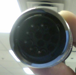

Visually inspect the male pins on the lamp cables and the female sockets on the front panel connectors.
- If male pin(s) are pushed in, pull them out carefully with a pair of tweezers or needle-nose pliers.
- If female socket(s) are pushed in,
- Turn off the control box.
- Unplug any and all cabling from the box (especially the AC cord)
- Undo the bolts that hold the front of the box to the frame using a 5/32" Allen/ball head driver
- Remove the box from the frame
- Remove the Phillips head 6-32 screws on the top of the box to slide off the lid
- Inspect the front panel ballast connectors and identify the "pushed in" sockets.
- With a pair of tweezers or pliers GENTLY push the sockets FULLY back inside of the connector (there is usually a discreet snapping sound when they successfully lock in place, but it's also OK to not hear it)
- Take a set of ballast cabling and try to mate the cable again to the front panel connectors and check to see if you are still able to push the sockets into the connector
- If successful, Replace the lid of the box, slide the box back into the rack, bolt the front of the box to the frame, then replace all of the cabling
-
Apply power to the box and retest lamps as needed.